| |
 |
|
|
 |
| |
|
|
| |
GARZO LIQUID LEVEL CONTROLLER INSTALLATION GUIDE
Basic Installation.
1. Determine the proper level to be maintained. Make sure that the adaptor or bracket has been mounted to assure proper level control.
|
2. The GARZO Model 108B series of self contained liquid level controllers senses the oil level within the
controller body and controls this level only. It is important that the controller body be properly
connected to the device to be controlled such that the two levels are equalized. The outlet device from
the controller to the engine crankcase, for example, must be of an adequate size to allow for the make
up oil to flow with a minimum pressure drop. The outlet connections on the controllers mounted with
adaptors are connected automatically. The outlet connections on controllers mounted with brackets
must be connected to an engine or compressor crankcase with no more than 2 ft of ¾" I.D. flexible
hose, tubing, or adjustable piping. The fluid must flow to the crankcase by gravity. When high flow
rates are involved, or when the oil is extremely viscous, consult factory for recommendations.
|
 |
| 3. Connect the inlet connection to the supply source with a minimum ¾" I.D. flexible hose, tubing, or
adjustable piping. In cold weather applications or in viscous fluid applications, there are appreciable
pressure drops between the source of oil supply and the controller inlet. The supply pressures on the
0-15 psig model should be approximately 2 psig minimum to 15 psig maximum. On the 70 psig model,
the inlet pressure should be from 10 psig minimum up to 70 psig maximum. |
|
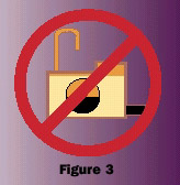 |
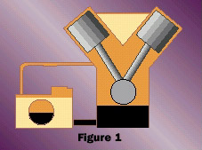
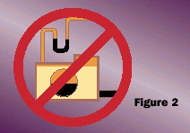
4. Most engines operate with either a negative or positive pressure in the crankcase. A flexible equalizing vent line must be run from the crankcase to the controller vent connection. Run a " I.D. minimum line from the vent connection to a point in the crankcase above the running oil level. (Figure 1) The vent line must be self draining such that oil cannot be trapped. (Figure 2) The vent line should not be vented to the atmosphere. (Figure 3) This line must also be run on those applications where the shutdown oil level is higher than the running level. Failure to do so might result in an incorrect level reading in the regulator. |
| 5. The controller is furnished with an inlet filter screen. This screen is designed to keep dirt and trash out of the controller float valve during initial startup and during normal operation. After initial startup, the filter screen should be checked and cleaned if necessary. Under some conditions of abnormally dirty oil, or with abnormally high water contamination, a larger filter should be installed in the system. Consult the factory for a recommendation. |
|
|
| |
|
|
|
|
|
|
|
|